Lab: AXI4-Burst Mode (m_axi)
Simple example of AXI4-Burst Mode
This lab is an example of AXI4 data transfer in burst mode. It takes in a given sample of values and provides the square root.
1) Vitis HLS: Generating RTL code from C/C++ code
In this section you learn how to use the Vitis HLS command line to synthesize your code and generate RTL.
1.1) Download the source code
Find the code here. This is the code we will be using:
#include "axi4_sqrt.hpp"
#include <string.h>
#include <math.h>

void axi4_sqrt(float *in, float *out, int len)
{
#pragma HLS INTERFACE s_axilite port=return bundle=sqrt
#pragma HLS INTERFACE s_axilite port=len bundle=sqrt
#pragma HLS INTERFACE m_axi depth=50 port=out offset=slave bundle=output
#pragma HLS INTERFACE m_axi depth=50 port=in offset=slave bundle=input
#pragma HLS INTERFACE s_axilite port=in bundle=sqrt
#pragma HLS INTERFACE s_axilite port=out bundle=sqrt

        float buff[100];
        memcpy(buff, (const float*) in, len * sizeof(float));

        for(int i = 0; i < len; i++)
                buff[i] = sqrt(buff[i]);

        memcpy(out, (const float*) buff, len * sizeof(float));
}
AXI bursts and interface pragmas
An AXI4 burst can transfer multiple data beats with one address request, reducing address overhead. Here, memcpy exposes consecutive memory accesses that HLS can implement as bursts; suitable loops can do this too. One copy may require several bursts.
inandoutare memory-mapped managers. Their differentbundlenames create separate AXI interfaces.offset=slaveexposes each buffer’s base address through an AXI-Lite register for the host to program.s_axilite ... bundle=sqrtgroups those addresses,len, and start/done control into one control interface.depth=50sizes each pointer’s C/RTL co-simulation buffer for 50 floats. This parameter does not set burst length.In this example, burst length can be affected by
len, or can be specified by pragmasmax_read_burst_lengthandmax_read_burst_length.
See the AMD interface pragma reference for details.
1.2) Generate RTL code and export it
Source your Vitis 2024.2 environment, then run these commands from the repository root:
cd project_files/lab_axi_burst/axi4_burst
make hls    # Generate RTL with C synthesis
make report # Copy the synthesis report
make sim    # Run C simulation
make cosim  # Optional C/RTL co-simulation
make ip     # Export the Vivado IP
The __hls_config__.ini file selects the PYNQ-Z2 part and a 10 ns clock period. The Makefile applies config_interface -m_axi_addr64=false so the AXI master addresses are 32 bits, matching the host register writes below.
Check axi4_sqrt_csynth.rpt for resource utilization and timing. Your latency is unknown (?) because your loop size (len) is a variable. The AXI-Lite register offsets are listed under “S_AXILITE Registers” in axi4_sqrt.comp/hls/syn/report/csynth.rpt.
make ip exports the IP to axi4_sqrt.comp/hls/impl/ip, including the packaged xilinx_com_hls_axi4_sqrt_1_0.zip.
2) Vivado: Generating bitstream from RTL code
In this section we import our RTL code from last section, add some required IPs, and generate our bitstream.
2.1) Create a new Vivado project
Open your Vivado tool and create a new project. Select an appropriate location for your project and leave the default project name as is (project_1).
Select RTL Project and check Do not specify sources at this time.
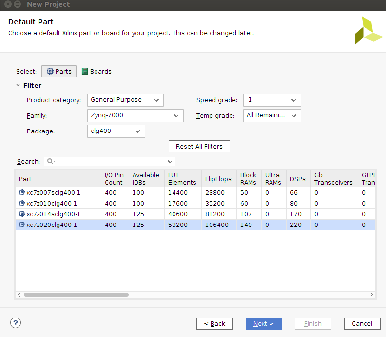
Select xc7z020clg400-1 for your part:
2.2) Import RTL code
Under Flow Navigator, click on IP Catalog. Right-click on the opened window and select Add Repository. Navigate to your Vitis HLS component > hls > impl > ip (axi4_sqrt.comp/hls/impl/ip) and select it:

2.3) Add IPs to your design
Under Flow Navigator, click on Create Block Design. Leave the design name as is (design_1). In the newly opened window, you can add IPs by clicking on the plus sign.
Add ZYNQ7 Processing System to your design:
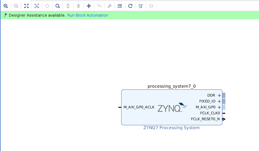
Double click on ZYNQ7 IP to customize it. In the opened window, double click on High Performance AXI 32b/64b Slave Parts:
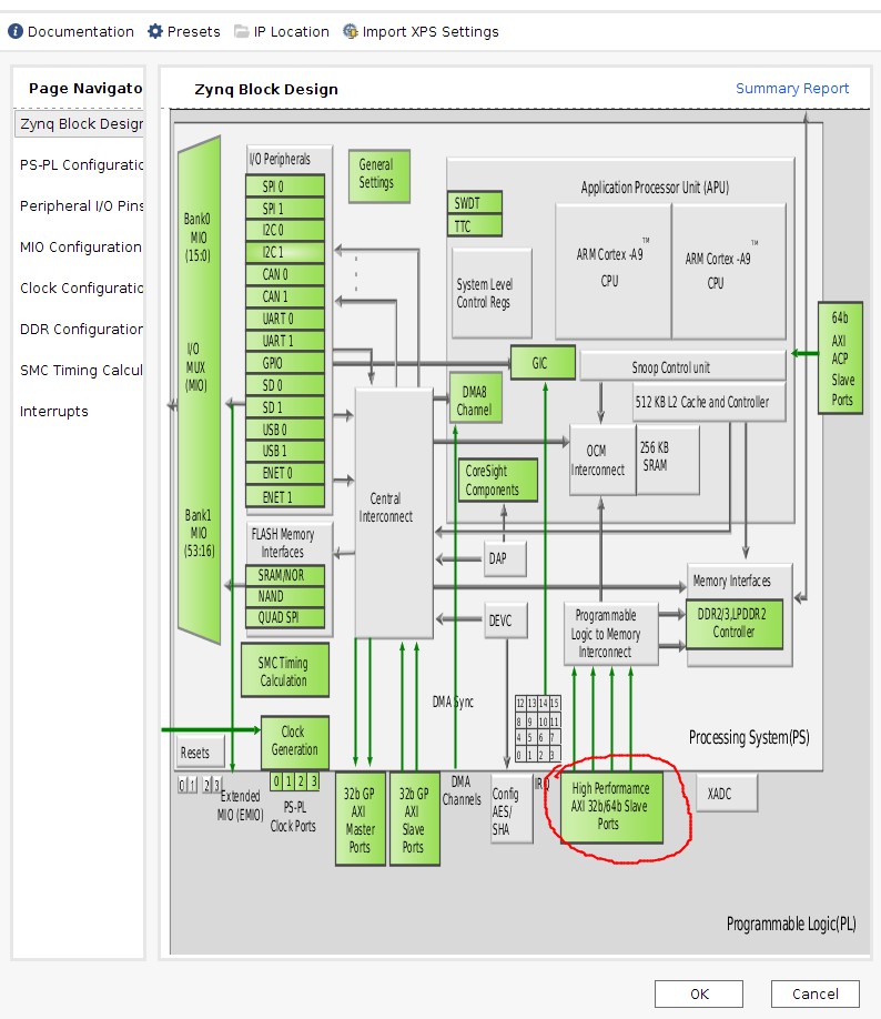
Select and check S AXI HP0 interface:

Add the axi4_sqrt IP to the design.

2.4) Automatic connections
Click on Run Block Automation
Click on Run Connection Automation and select all. Click OK.

Click on Run Connection Automation again and select all. Click OK.

This is how the final design should look. Note: in Vivado 2023, it uses AXI Interconnect block instead of AXI SmartConnect, but it works.

2.5) Generate bitstream
Save your design CTRL+S or File > Save Block Design.
Validate your design: Tools > Validate Design.
In Sources, right click on design_1, and Create HDL Wrapper. Now you should have design_1_wrapper.
Generate bitstream by clicking on Generate Bitstream in Program and Debug.
2.6) Post bitstream Generation
In sources, expand design_1_wrapper::design_1_i::design_1::axi4_sqrt_0::design_1_axi4_sqrt_0_0::inst : axi4_sqrt, double click on axi4_sqrt_sqrt_s_axi_U , and note the address for in_r , out_r , len as 0x10 , 0x18 and 0x20 respectively. We need this addresses in our host program. These addresses can also be found in the Vitis HLS C Synthesis summary.

You can close and exit the Vivado tool.
Copy your project directory > project_1 > project_1.runs > impl_1 > design_1_wrapper.bit to your project directory > project_1 and rename it to axi4_sqrt.bit
Copy your project directory > project_1 > project_1.gen > sources_1 > bd > design_1 > hw_handoff > design_1.hwh to your project directory > project_1 and rename it to axi4_sqrt.hwh
These files need to have the same name (except for their file extension).
3) Host program
In this section, we use Python to test our design.
3.1) Move your files
Create a new folder in your PYNQ board and move both axi4_sqrt.hwh and axi4_sqrt.bit into it.
3.2) Python code
Create a new Jupyter notebook and run the following code to test your design:
Use allocate for the buffers, flush the input before starting, and invalidate the output after ap_done. See the PYNQ allocation documentation.
from pynq import Overlay, allocate
import numpy as np

ol = Overlay('axi4_sqrt.bit')
sqrt_ip = ol.axi4_sqrt_0 # if you can't find the IP, type 'ol.' and hit Tab to see what options are available
length = 40
inpt = allocate(shape=(length,), dtype=np.float32)
outpt = allocate(shape=(length,), dtype=np.float32)
a = [i*i for i in range(length)]
np.copyto(inpt, a)
soft_op = np.sqrt(inpt)
inpt.flush()

sqrt_ip.write(0x20, length)
sqrt_ip.write(0x10, inpt.physical_address)
sqrt_ip.write(0x18, outpt.physical_address)
sqrt_ip.write(0x00, 1)  # AP_START
while (sqrt_ip.read(0x00) & 0x2) == 0:  # AP_DONE
    pass
outpt.invalidate()
np.testing.assert_allclose(outpt, soft_op, rtol=1e-5, atol=1e-5)

print("Hardware Output", "Software Output \n")
for i in range(length):
    print(outpt[i], "\t\t  ", soft_op[i])
inpt.freebuffer()
outpt.freebuffer()