Lab: MicroBlaze
Let’s take a look inside the BaseOverlay class which corresponds to the Overlay below:
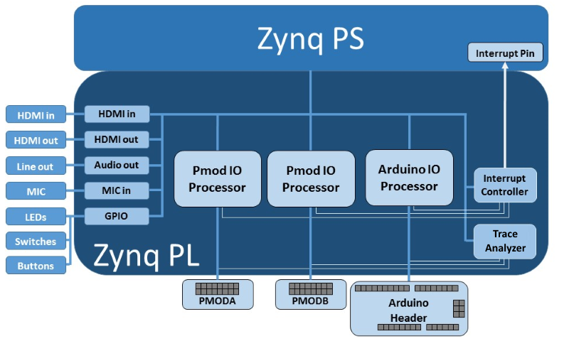
Let’s load the base overlay and check the IO Processors: iop_arduino, iop_pmoda, and iop_pmodb
[21]:
import pynq
from pynq.overlays.base import BaseOverlay

ol = BaseOverlay("base.bit")
[22]:
ol.ip_dict
[22]:
{'audio_direct_0': {'addr_range': 65536,
  'driver': pynq.lib.audio.AudioDirect,
  'fullpath': 'audio_direct_0',
  'gpio': {'sel_direct': {'index': 3,
    'pins': {'audio_direct_0/sel_direct', 'audio_path_sel/Dout'},
    'state': None}},
  'interrupts': {},
  'phys_addr': 1136656384,
  'state': None,
  'type': 'xilinx.com:user:audio_direct:1.1'},
 'btns_gpio': {'addr_range': 65536,
  'driver': pynq.lib.axigpio.AxiGPIO,
  'fullpath': 'btns_gpio',
  'gpio': {},
  'interrupts': {'ip2intc_irpt': {'controller': 'system_interrupts',
    'fullpath': 'btns_gpio/ip2intc_irpt',
    'index': 11}},
  'phys_addr': 1092681728,
  'state': None,
  'type': 'xilinx.com:ip:axi_gpio:2.0'},
 'iop_arduino/mb_bram_ctrl': {'addr_range': 65536,
  'fullpath': 'iop_arduino/mb_bram_ctrl',
  'gpio': {},
  'interrupts': {},
  'phys_addr': 1140850688,
  'state': None,
  'type': 'xilinx.com:ip:axi_bram_ctrl:4.0'},
 'iop_pmoda/mb_bram_ctrl': {'addr_range': 65536,
  'fullpath': 'iop_pmoda/mb_bram_ctrl',
  'gpio': {},
  'interrupts': {},
  'phys_addr': 1073741824,
  'state': None,
  'type': 'xilinx.com:ip:axi_bram_ctrl:4.0'},
 'iop_pmodb/mb_bram_ctrl': {'addr_range': 65536,
  'fullpath': 'iop_pmodb/mb_bram_ctrl',
  'gpio': {},
  'interrupts': {},
  'phys_addr': 1107296256,
  'state': None,
  'type': 'xilinx.com:ip:axi_bram_ctrl:4.0'},
 'leds_gpio': {'addr_range': 65536,
  'driver': pynq.lib.axigpio.AxiGPIO,
  'fullpath': 'leds_gpio',
  'gpio': {},
  'interrupts': {},
  'phys_addr': 1092943872,
  'state': None,
  'type': 'xilinx.com:ip:axi_gpio:2.0'},
 'rgbleds_gpio': {'addr_range': 65536,
  'driver': pynq.lib.axigpio.AxiGPIO,
  'fullpath': 'rgbleds_gpio',
  'gpio': {},
  'interrupts': {},
  'phys_addr': 1092878336,
  'state': None,
  'type': 'xilinx.com:ip:axi_gpio:2.0'},
 'switches_gpio': {'addr_range': 65536,
  'driver': pynq.lib.axigpio.AxiGPIO,
  'fullpath': 'switches_gpio',
  'gpio': {},
  'interrupts': {'ip2intc_irpt': {'controller': 'system_interrupts',
    'fullpath': 'switches_gpio/ip2intc_irpt',
    'index': 12}},
  'phys_addr': 1092616192,
  'state': None,
  'type': 'xilinx.com:ip:axi_gpio:2.0'},
 'system_interrupts': {'addr_range': 65536,
  'driver': pynq.overlay.DefaultIP,
  'fullpath': 'system_interrupts',
  'gpio': {},
  'interrupts': {},
  'phys_addr': 1098907648,
  'state': None,
  'type': 'xilinx.com:ip:axi_intc:4.1'},
 'trace_analyzer_arduino/axi_dma_0': {'addr_range': 65536,
  'fullpath': 'trace_analyzer_arduino/axi_dma_0',
  'gpio': {},
  'interrupts': {'s2mm_introut': {'controller': 'system_interrupts',
    'fullpath': 'trace_analyzer_arduino/axi_dma_0/s2mm_introut',
    'index': 7}},
  'phys_addr': 2151743488,
  'state': None,
  'type': 'xilinx.com:ip:axi_dma:7.1'},
 'trace_analyzer_arduino/trace_cntrl_64_0': {'addr_range': 65536,
  'fullpath': 'trace_analyzer_arduino/trace_cntrl_64_0',
  'gpio': {},
  'interrupts': {},
  'phys_addr': 2210398208,
  'state': None,
  'type': 'xilinx.com:hls:trace_cntrl_64:1.4'},
 'trace_analyzer_pmoda/axi_dma_0': {'addr_range': 65536,
  'fullpath': 'trace_analyzer_pmoda/axi_dma_0',
  'gpio': {},
  'interrupts': {'s2mm_introut': {'controller': 'system_interrupts',
    'fullpath': 'trace_analyzer_pmoda/axi_dma_0/s2mm_introut',
    'index': 6}},
  'phys_addr': 2151677952,
  'state': None,
  'type': 'xilinx.com:ip:axi_dma:7.1'},
 'trace_analyzer_pmoda/trace_cntrl_32_0': {'addr_range': 65536,
  'fullpath': 'trace_analyzer_pmoda/trace_cntrl_32_0',
  'gpio': {},
  'interrupts': {},
  'phys_addr': 2210463744,
  'state': None,
  'type': 'xilinx.com:hls:trace_cntrl_32:1.4'},
 'video/axi_vdma': {'addr_range': 65536,
  'fullpath': 'video/axi_vdma',
  'gpio': {},
  'interrupts': {'mm2s_introut': {'controller': 'system_interrupts',
    'fullpath': 'video/axi_vdma/mm2s_introut',
    'index': 1},
   's2mm_introut': {'controller': 'system_interrupts',
    'fullpath': 'video/axi_vdma/s2mm_introut',
    'index': 0}},
  'phys_addr': 1124073472,
  'state': None,
  'type': 'xilinx.com:ip:axi_vdma:6.3'},
 'video/hdmi_in/color_convert': {'addr_range': 65536,
  'fullpath': 'video/hdmi_in/color_convert',
  'gpio': {},
  'interrupts': {},
  'phys_addr': 1136984064,
  'state': None,
  'type': 'xilinx.com:hls:color_convert:1.0'},
 'video/hdmi_in/frontend/axi_gpio_hdmiin': {'addr_range': 65536,
  'fullpath': 'video/hdmi_in/frontend/axi_gpio_hdmiin',
  'gpio': {},
  'interrupts': {'ip2intc_irpt': {'controller': 'system_interrupts',
    'fullpath': 'video/hdmi_in/frontend/axi_gpio_hdmiin/ip2intc_irpt',
    'index': 4}},
  'phys_addr': 1092747264,
  'state': None,
  'type': 'xilinx.com:ip:axi_gpio:2.0'},
 'video/hdmi_in/frontend/vtc_in': {'addr_range': 65536,
  'fullpath': 'video/hdmi_in/frontend/vtc_in',
  'gpio': {},
  'interrupts': {'irq': {'controller': 'system_interrupts',
    'fullpath': 'video/hdmi_in/frontend/vtc_in/irq',
    'index': 3}},
  'phys_addr': 1136852992,
  'state': None,
  'type': 'xilinx.com:ip:v_tc:6.1'},
 'video/hdmi_in/pixel_pack': {'addr_range': 65536,
  'fullpath': 'video/hdmi_in/pixel_pack',
  'gpio': {},
  'interrupts': {},
  'phys_addr': 1136918528,
  'state': None,
  'type': 'xilinx.com:hls:pixel_pack:1.0'},
 'video/hdmi_out/color_convert': {'addr_range': 65536,
  'fullpath': 'video/hdmi_out/color_convert',
  'gpio': {},
  'interrupts': {},
  'phys_addr': 1137049600,
  'state': None,
  'type': 'xilinx.com:hls:color_convert:1.0'},
 'video/hdmi_out/frontend/axi_dynclk': {'addr_range': 65536,
  'fullpath': 'video/hdmi_out/frontend/axi_dynclk',
  'gpio': {},
  'interrupts': {},
  'phys_addr': 1136721920,
  'state': None,
  'type': 'digilentinc.com:ip:axi_dynclk:1.0'},
 'video/hdmi_out/frontend/hdmi_out_hpd_video': {'addr_range': 65536,
  'fullpath': 'video/hdmi_out/frontend/hdmi_out_hpd_video',
  'gpio': {},
  'interrupts': {'ip2intc_irpt': {'controller': 'system_interrupts',
    'fullpath': 'video/hdmi_out/frontend/hdmi_out_hpd_video/ip2intc_irpt',
    'index': 5}},
  'phys_addr': 1092812800,
  'state': None,
  'type': 'xilinx.com:ip:axi_gpio:2.0'},
 'video/hdmi_out/frontend/vtc_out': {'addr_range': 65536,
  'fullpath': 'video/hdmi_out/frontend/vtc_out',
  'gpio': {},
  'interrupts': {'irq': {'controller': 'system_interrupts',
    'fullpath': 'video/hdmi_out/frontend/vtc_out/irq',
    'index': 2}},
  'phys_addr': 1136787456,
  'state': None,
  'type': 'xilinx.com:ip:v_tc:6.1'},
 'video/hdmi_out/pixel_unpack': {'addr_range': 65536,
  'fullpath': 'video/hdmi_out/pixel_unpack',
  'gpio': {},
  'interrupts': {},
  'phys_addr': 1137115136,
  'state': None,
  'type': 'xilinx.com:hls:pixel_unpack:1.0'}}
Some PMODs already have drivers: list of plug and play PMODs
[26]:
from pynq.lib import Pmod_OLED
pmod_oled = Pmod_OLED(ol.PMODA)
[27]:
pmod_oled.clear()
pmod_oled.write('Welcome to \n\nPYNQ!')
Let’s take a look at it’s code on pynq github
Hello World on Microblaze
IO prrocessors can also be used for running small applications.
IPYthon magic allow the execution of Non-Python code in a Python cell.
[2]:
from pynq.lib import MicroblazeLibrary
[ ]:
%%microblaze ol.PMODA
#include <pyprintf.h>

int mb_print(){
    pyprintf("Hello World!");
    return 0;
}
[ ]:
mb_print()
Task 1
Here you learn how to use provided python libraries.
Using the source code for RGBLED write a for loop to change the coloring of your rgb leds between red, blue, and white similar to a police light bar. You can use time.sleep as delay between flashes.
[ ]:
import time
# write code for RGBLED
Task 2
Write a microblaze code to calculate factorial of an input on PL. Your result should be same as the python code output.
[ ]:
%%microblaze ol.PMODB

int mb_fact(int in){
//write code here
}
[ ]:
inp = 10

print('out = {}'.format(mb_fact(inp))) # your function is called here, note the function prototype

ff=1
for i in range(1,inp+1):
    ff = ff*i
print('ans = {}'.format(ff))
Task 3
Use the source code for OLED_PMOD to learn how to use the GPIO pins.
Write two microblaze functions: mba_send(v) and mbb_recv() to send 1-bit accross the two PMODs A and B.
You need to connect pin 0 of the two PMODs using a jumper wire.
[7]:
%%microblaze ol.PMODA
#include <gpio.h>

int mba_send(int v){
//write code here
}
[15]:
%%microblaze ol.PMODB
#include <gpio.h>

int mbb_recv(){
//write code here
}
[19]:
mba_send(1)
print(mbb_recv())
1
Task 4
Read voltages from the Pmod_AD2. Since there are only 2 Pmod_AD2. Write the code to the best of your ability and ask one of the TA’s to check before testing on the Pmod_AD2.
The first part of this task is to only use the pynq python libraries. You can reference the API here. Remember to close the pmod instance
[20]:
# write code here
For the second part of the task, we’ll see how to communicate with the Pmod_AD2 by programming the microblaze in C. While this is more work, most of the PMODS we have available do not have python libraries pre-built so you’ll need to search through the documentation and program the microblaze in order to use them.
[ ]:
%%microblaze base.PMODA
#include <i2c.h>
#include <pyprintf.h>

//TODO: Find the pmod_ad2 address value
#define AD2IICAddr         <#>

//Configuration
#define CH3                 7
#define CH2                 6
#define CH1                 5
#define CH0                 4
#define REF_SEL             3
#define FLTR                2
#define BitTrialDelay       1
#define SampleDelay         0

#define BitMask             0xFFF

float read_i2c() {

    //TODO: open a new i2c device

    unsigned char WriteBuffer[1];
    unsigned char cfgValue = (1 << CH3)   |
               (1 << CH2)                 |
               (1 << CH1)                 |
               (1 << CH0)                 |
               (0 << REF_SEL)             |
               (0 << FLTR)                |
               (0 << BitTrialDelay)       |
               (0 << SampleDelay);
    WriteBuffer[0]=cfgValue;
    //TODO: write the configuration to the pmod (1 byte)

    //Receiving data.
    unsigned char rcvbuffer[2];
    int rxData;
    //TODO: read from the pmod and format the raw data (2 bytes)
    // The first byte is MSB, while the second byte is LSB
    rxData = //;


    //Format as a voltage
    int raw = (rxData & BitMask);
    return (float)(raw * 2.00 / 4096.0); // 2.0 V is the reference voltage for the AD2 Pmod.
}