Lab: Axistream Multiple DMAs (axis)
Simple streaming example with multiple inputs & outputs
In this example we learn how to use Xilinx AXI_DMA to create a simple floating point adder with two streaming inputs and two streaming outputs.
1) Vitis HLS: Generating RTL code from C/C++ code
Find the code here. The main body of our design is a simple floating point adder and subtractor.
We use AXI-Stream, the most common on-chip communication protocol for high performance accelerator design in SoC environments. Unlike the AXI-Lite interfaces, AXI-Stream interfaces do not have address channels, and are designed for high throughput data transfer.
Defining the interfaces is a bit more complicated here. First we have to define a transaction packet that can be understood by AXI-Stream protocol,
typedef hls::axis<float, 0,0,0> transPkt;
float is our data type, the other parameters are for side channels, it’s safe to just leave them as 0 for this lab.
The interfaces to our top function must be defined as AXI-Stream channels:
void axis_fp_example(
        hls::stream<transPkt>&A,
        hls::stream<transPkt>&B,
        hls::stream<transPkt>&C,
        hls::stream<transPkt>&D
);
From a software perspective, you can think of these interfaces as FIFO queues with unkown depth. You can read from an input stream when there is a packet available, and write to an output stream when you have the data ready. For example,
Apkt = A.read();
Bpkt = B.read();
Adata = Apkt.data;
Bdata = Bpkt.data;
Apkt.data = Cdata;
Bpkt.data = Ddata;
// Re-use the input packets to preserve side channel signals
C.write(Apkt);
D.write(Bpkt);
The most important optional side channel signal is last (named TLAST in actual hardware). This indicates the end of a stream of data. In most cases people hope the accelerator to keep processing data until the end of the input stream. In this lab, we set the program for loop to run indefinitely until it receive the last input packet, which comes with a high last signal.
It’s important to handle the side channels properly to prevent DMAs from hanging. One easy way is to just re-use the input packets for output as shown above.
axis_fp_example_test.cpp is a simple software testbench. Note that since both read() and write() functions are blocking, we have to write all the input data to the input stream before calling the function. This is different from hardware execution.
As we did in lab1, use command make ip to run C simulation, C synthesis, and export RTL as an IP core for Vivado.
2) Vivado: Generating bitstream from RTL code
In this section we import our RTL code from last section, add some required IPs, and generate our bitstream
2.1) Create a new Vivado project and import RTL code
Follow the same steps for creating a Vivado project and add the ip folder in the Vitis HLS project to Vivado IP catalog as in lab 1.
Open your Vivado tool and create a new project. Select an appropriate location for your project and leave the default project name as is (project_1).
Select RTL Project and check Do specify not sources at this time.
Select xc7z020clg400-1 for your part
Under Flow Navigator, click on IP Catalog. Right click on the opened window and select Add Repository. Navigate to your Vitis HLS Component > hls > impl > ip and select it:
2.2) Add IPs to your design
Under Flow Navigator, click on Create Block Design. Leave the design name as is (design_1). In the newly opened window you can add IPs by clicking on the plus sign.
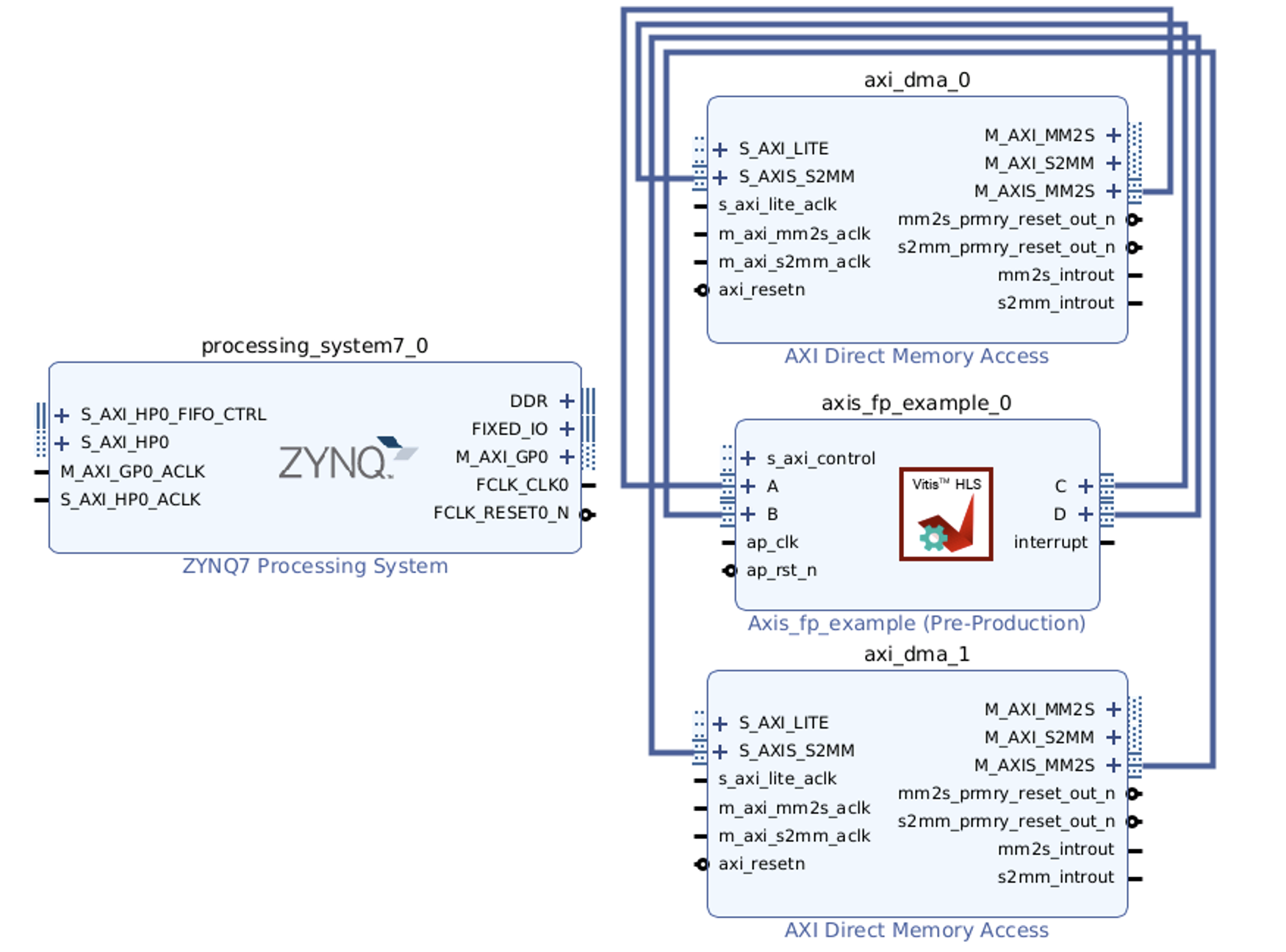
Add ZYNQ7 Processing System and our HLS ip core to your design:

Note that the input and output ports of our HLS IP are all AXI-Stream ports.
Double click on ZYNQ7 IP to customize it. In the opened window, double click on High Performance AXI 32b/64b Slave Parts:
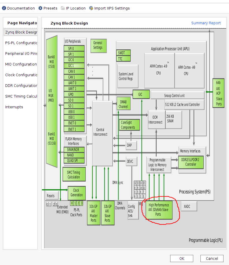
Select and check S AXI HP0 interface:

Since AXI-Stream ports do not have address channels, we need to use AXI DMAs to tranfer data between our HLS IP and the DDR memory. One DMA can handle one read and one write channel. Therefore, we need to add 2 DMAs to our design.

Double click the DMA to configure: uncheck Enable Scatter Gather Engine. Both DMAs will need read and write channels.

2.4) Manual connections
AXI Stream ports need to be connected manually. We start from the M_AXIS_MM2S port of axi_dma_0. This channel will read data from DDR memory and send to our HLS IP. Vivado will automatically show you the elegible ports to be connected to.

The S_AXIS_S2MM channels will receive data from our HLS IP and write to DDR memory. They should connected to the output ports.
Complete all AXI-Stream connections as below:
2.5) Automatic connections
Now you can leave the rest of the connections to the tool. There should be a highlighted strip on top of your diagram window.
Click on Run Block Automation to enable the external FIXED_IO and DDR interfaces:

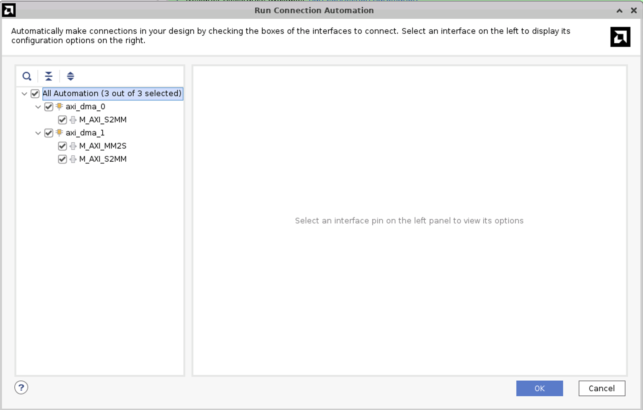
Click on Run Connection Automation and select all.

IMPORTANT! you have to click again on Run Connection Automation
At this point, your design should contain 2 AXI-interconnects. One of them connects the M_AXI port of the PS with the S_AXI_LITE ports of the 2 DMAs and our HLS IP. This enables the PS to configure these IPs. Your entire block diagram should look like this:

The other connect the M_AXI ports of the DMAs to the high performance S_AXI port(s) of the PS. DMAs use this channel to perform read and write with the memory.
2.6) Generate bitstream
Follow the same step as as lab 1.
Save your design CTRL+S or File > Save Block Design.
Validate your design: Tools > Validate Design
In Sources, right click on design_1, and Create HDL Wrapper. Now you should have design_1_wrapper.v
Generate bitstream by clicking on Generate Bitstream in Flow Navigator
After the above steps finish, keep your project directory > project_1 > project_1.runs > impl_1 > design_1_wrapper.bit and project directory > project_1 > project_1.gen > sources_1 > bd > design_1 > hw_handoff > design_1.hwh for Pynq implementation. You should make sure that the bitstream and the hardware handoff files have the same name.
You can close and exit from Vivado tool.
3) Host program
In this section we use Python to test our design.
3.1) Move your files
Create a new folder in your PYNQ board and move both bitstream and hardware handoff into it.
3.2) Python code
Create a new Jupyter notebook and run code in ./simple_add_float.ipynb under the source code folder to test your design.
You should be able to see all the components of the overlay by checking its IP dictionary
ol = Overlay("./design_1.bit")
ol.ip_dict
In this lab, we are only using axi_dma_0, axi_dma_1 and our HLS IP.
You can check the register map of the HLS IP, and start the IP by writing to the corresponding register:
CONTROL_REGISTER = 0x0
hls_ip.write(CONTROL_REGISTER, 0x1) # 0x81 will set bit 0
hls_ip.register_map
It is recommended to start the receive process first.
dma0_recv.transfer(output_buffer0)
dma1_recv.transfer(output_buffer1)
dma0_send.transfer(input_buffer0)
dma1_send.transfer(input_buffer1)
dma0_send.wait()
dma1_send.wait()
dma0_recv.wait()
dma1_recv.wait()
Check the register map of DMAs to find out whether the transfer has finished without error, which is very useful in debugging.
dma0.register_map