Lab: Interrupts
Interrupt Controller
In this example we implement \(f(x)=x!\) as an IP for PYNQ with interrupt controller.
1) Vivado HLS: C/C++ to RTL
In this section, you will write your code in C/C++ and convert it to RTL using Vivado HLS.
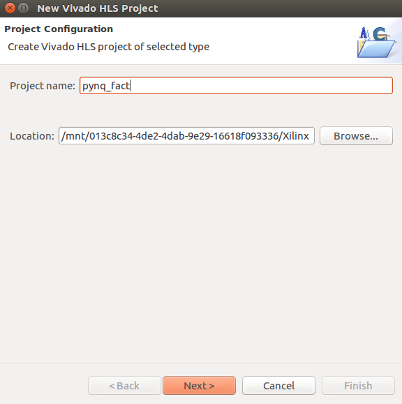
1.1) Create a project
Open the Vivado HLS tool, create a new project, and name it pynq_fact.
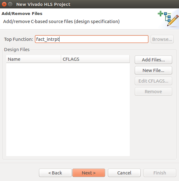
Set top function to fact_intrpt.
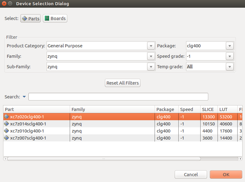
Select xc7z020clg400-1 as your part number.
1.2) Write your code
In Explorer section, right click on Source, and select new file. Create a new file and name it fact_intrpt.cpp**and set **in, out, and return ports as s_axilite interfaces. Your code should look like this:
#pragma HLS INTERFACE s_axilite port=in bundle=control
#pragma HLS INTERFACE s_axilite port=out bundle=control
#pragma HLS INTERFACE s_axilite port=return bundle=control

void fact_intrpt(int* out, int in){
    int i, k=1;
    for(i=1; i<=in; i++){
        k = k*i;
    }
    *out = k;
}
If you run in to II violations (like Vitis 2021 always does) set II=2:
#pragma HLS pipeline II=2
1.3) Synthesize your code and export RTL
You can synthesize your code by clicking on C Synthesis. After finishing C synthesis, click on Export RTL and select Vivado IP (.zip). Now that you exported your RTL, you can close Vitis HLS.
2) Vivado: RTL to Bitstream
In this section we generate a bitstream for our IP.
2.1) Create a new project
Open the Vivado tool and create a new project and name it fact_pynq.
Select RTL Project and check Do not specify sources at this time.
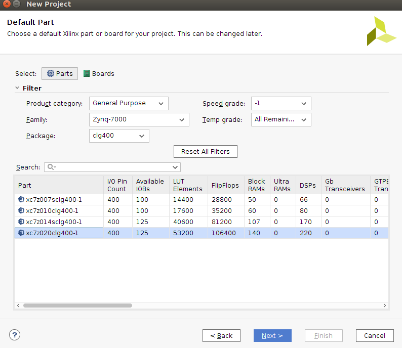
Set your part number to xc7z020clg400-1:
2.2) Import RTL
In Flow Navigator, under Project Manager, click on IP Catalog.
On the newly opened window, right click and select Add Repository. Select your extracted Vivado IP that you exported from Vitis.
2.3) Add blocks to your design
In Flow Navigator, under IP Integrator, click on Create Block Design. Leave the name as is, design_1.
You can add IPs to your design by clicking on the + sign. Add the following IPs:
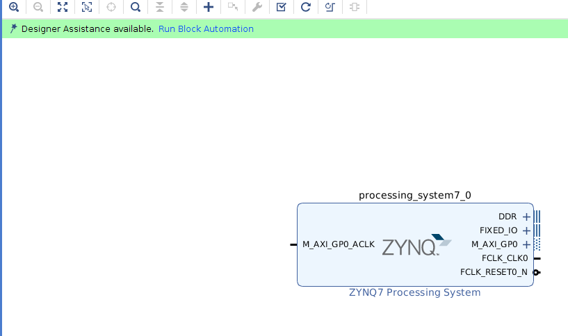
Add ZYNQ7 Processing System to your design:
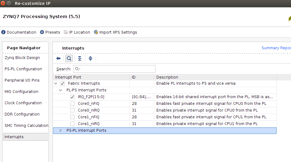
Double click on ZYNQ7 IP to customize it. Under page navigator, got to interrupts, and enable IRQ_F2P[15:0]
Add fact_intrpt and rename it to fact_intrpt:
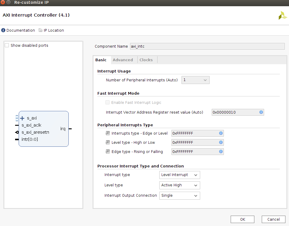
Add AXI Interrupt Controller and rename it to axi_intc:
Double click on axi_intc to customize it. Set Interrupt Output Connection to Single.
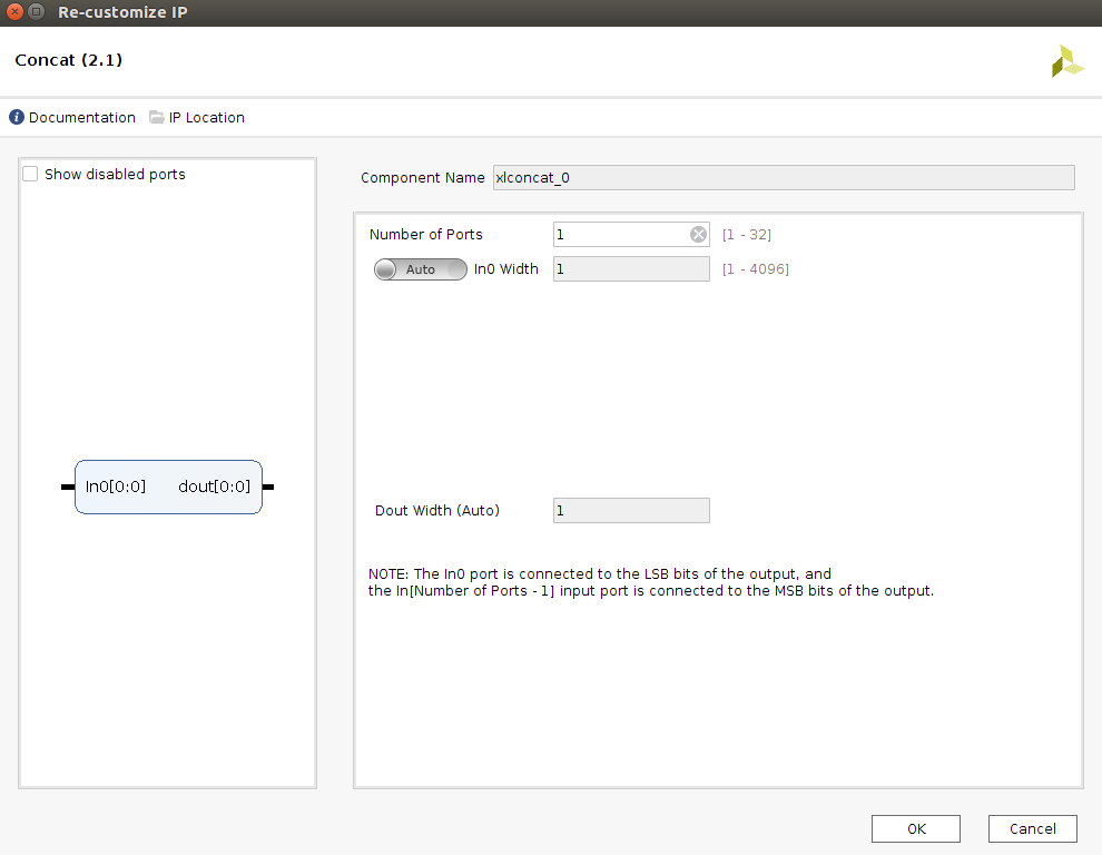
Add two Concat IPs to your design, double click on them for customization, and set Number of Ports to 1:
2.4) Connect your blocks
Connect the following ports:
fact_intrpt::interrupt to xlconcat_0::in0
xlconcat_0::dout to axi_intc::intr[0:0]
axi_intc::irq to xlconcat_1::in0
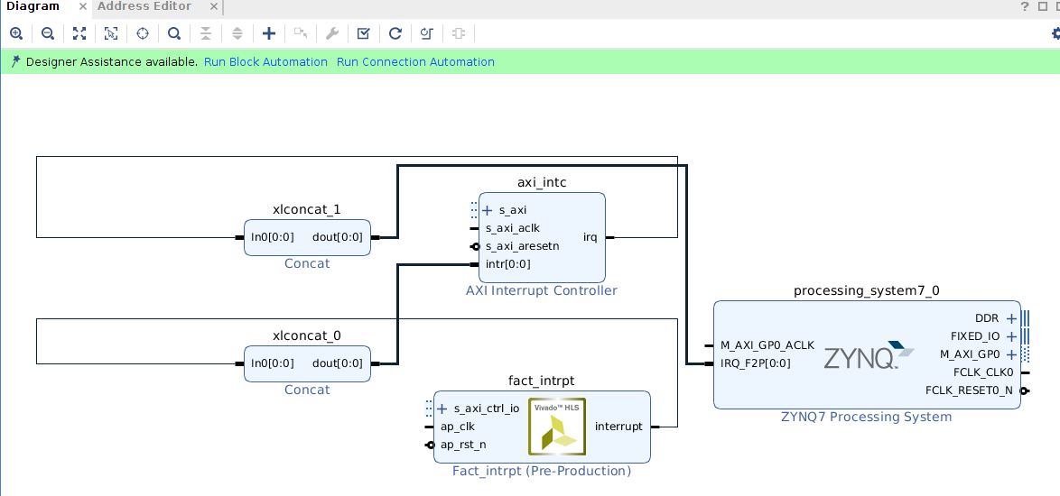
That is all the manual labor you have to do for the connections. Now, you can use the tool for the rest of the blocks and connections.
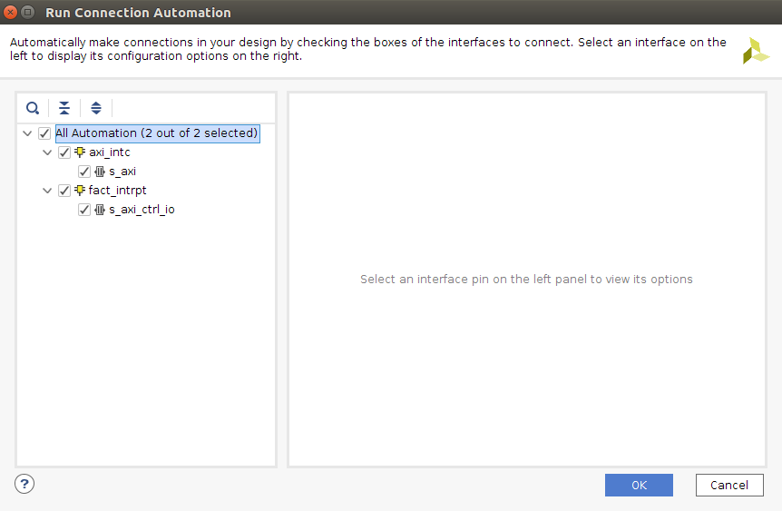
In the Diagram window, in the highlighted are, click on Run Block Automation. Then click on Run Connection Automation and select all:
Your design should look like the following:

2.5) Generating bitstream
Save your block diagram and check your design from Tools > Validate Design. If it passed successfully, under Sources, right click on design_1, and select Create HDL Wrapper with default settings.
Now you can click on Generate Bitstream in Flow Navigator with default settings to generate your bitstream.
2.6) Export .tcl file and note addresses
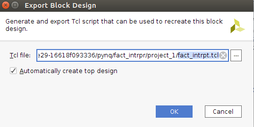
Exporting the block design is an optional step, Pynq seems to prefer .hwh over .tcl. After finishing your bitstream generation, you can export your block design from File > Export > Export Block Design, and name it fact_intrpt.tcl:
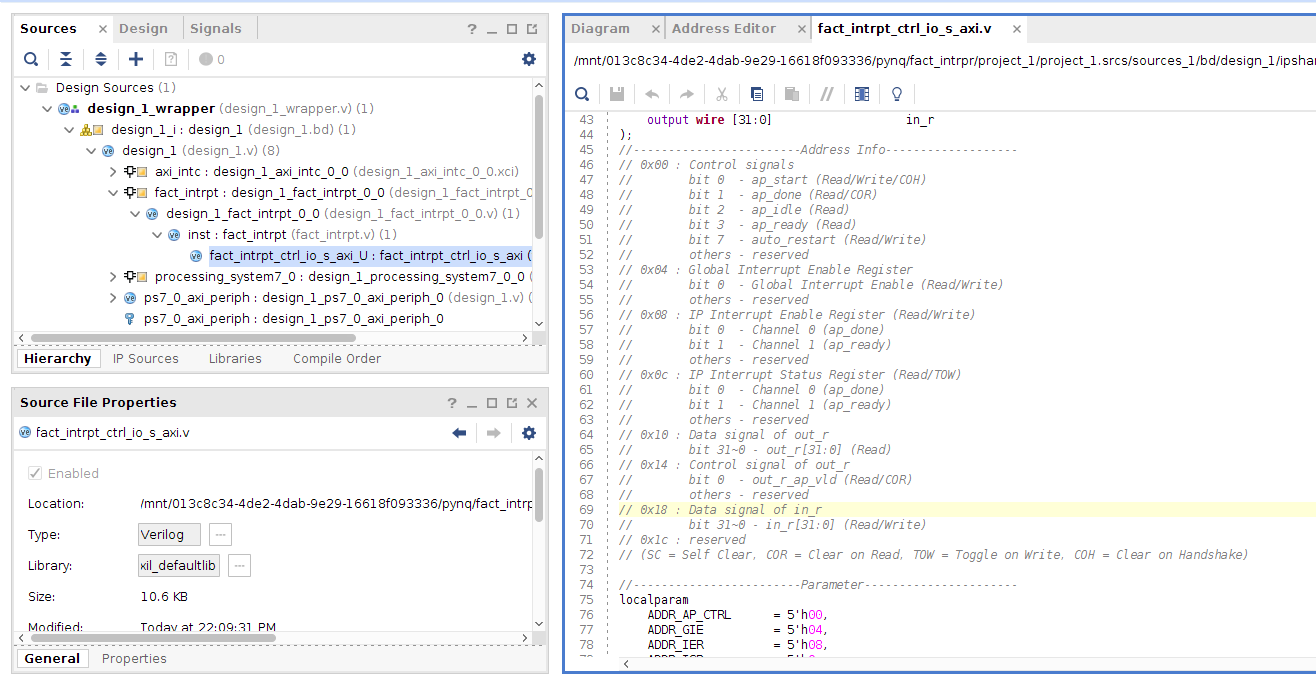
Navigate to your Vivado project folder and search for .bit and then for .hwh. Copy design_1_wrapper.bit (rename to design_1.bit) and design_1.hwh. In Sources, open fact_intrpt_cntrl_io_s_axi.v and copy the address info into a text file. We need these addresses to map our variables in the Python code.
3) Host program
In this section we use a Jupyter notebook to interact with our IP.
3.1) Move files to PYNQ
Connect to your PYNQ board and create a new folder. Copy fact_intrpt.hwh and fact_intrpt.bit to this folder like we have done in previous labs. Create a new Jupyter notebook and complete it as following to interact with your design:
from pynq import Overlay
import asyncio
from psutil import cpu_percent

ol = Overlay("fact_intrpt.bit")
ol.download()
# IP's addresses
IP_CTRL = 0x00
AP_START = 0x1
GIER = 0x04
IP_IER = 0x08
IP_ISR = 0x0C
INTRPT_AP_DONE = 0x1
INTRPT_AP_READY = 0x2
OUT_REG = 0x10
INP_REG = 0x18

_INTRPT = INTRPT_AP_DONE

fact_ip = ol.fact_intrpt
fact_ip.write(GIER, 0x1)
fact_ip.write(IP_IER, _INTRPT)
# Coroutine that waits for an IP to be done.
async def read_ip(ip):
    while True:
        # Wait for the IP to finish.
        await ip.interrupt.wait()
        # Clear the interrupt and then print output's value.
        if (ip.read(IP_ISR) & _INTRPT):
            ip.write(IP_ISR, _INTRPT)
            print('interrupt received, out = {}'.format(ip.read(OUT_REG)))

# Task for IP using the coroutine
ip_task = asyncio.ensure_future(read_ip(fact_ip))

# Coroutine for writing input and starting the IP with delay
async def write_wait(interval):
    await asyncio.sleep(interval)
    # write to input
    fact_ip.write(INP_REG, 10)
    print("input = ", fact_ip.read(INP_REG))
    fact_ip.write(IP_CTRL, AP_START) # You can comment it out to test the interrupt
    print("IP started")
    await asyncio.sleep(interval)

# Run the event loop until the time interval expires
time_interval = 2  # time in seconds
loop = asyncio.get_event_loop()
write_task = asyncio.ensure_future(write_wait(time_interval))

# Using psutil to record CPU utilization.
cpu_percent(percpu=True)  # Initializing the CPU monitoring.
loop.run_until_complete(write_task)
cpu_used = cpu_percent(percpu=True)

# Printing the CPU utilization
print('CPU Utilization = {cpu_used}'.format(**locals()))

# Removing the IP task from the event loop.
ip_task.cancel()
If you run into overlay issues run the following to display IP hierarchy in the overlay and select appropriately:
for i in ol.ip_dict:
        print(i)
You should see the following output:

That’s it for the lab.